Vapor transmission
How condensation water is formed
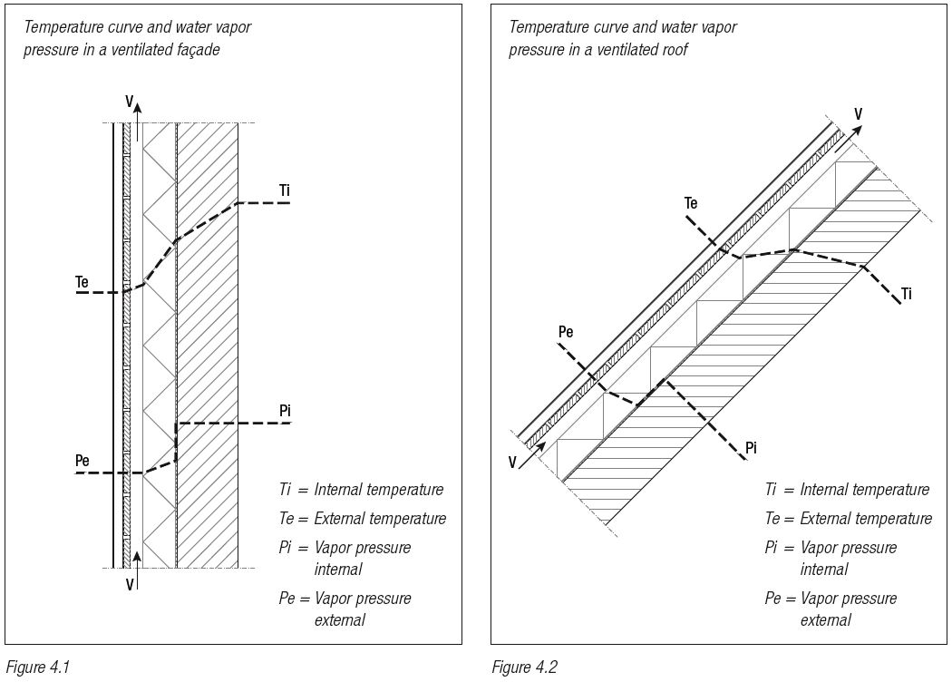
Structures are stressed not only by mechanical forces but also by the physical aspects of a building, such as fluctuating temperatures, which may vary between – 20 °C and + 80 °C, and differences in air humidity on the inside and outside.
In the most common, where the internal temperature (Ti) is higher than the external temperature (Te), it is generally also found that the air humidity is greater on the inside than the outside.
The difference in vapor pressure (Pi – Pe) causes vapor to be transported through the roof structure from the inside to the outside. If the roof is not constructed properly, condensation or frost will form on the inside of the relatively cold titanium zinc.

Damage and prevention
Excessive condensation can be harmful in a number of ways. For example, it can damage the titanium zinc on the backside as the result of corrosion, or lead to moisture damage on parts of the supporting structure (corrosion, wood rot or mold). Totally sealing the roof on the inside is not the answer: this cannot be done in practice, and in terms of moisture regulation in a building it is generally not desirable. In order to achieve the desired movement of vapor and to avoid the risk of damage, two main steps must be taken:
A. Fit a damp control course on the inside of the thermal insulation.
B. Include a gap on the external side of the thermal insulation to permit ventilation by external air.
A. Diffusion layer
This layer is necessary:
1. To let through just enough vapor, but not too much, to remove excess vapor from the building (e.g. vapor produced by the occupants). We recommend the selection of a material which prevents the transmission of vapor, having a minimum Sd-value of 10.
2. To make the structure draught-proof and prevent air from the interior from flowing directly into the ventilation cavity. The cavity is in direct contact with the external air, meaning an unpleasant current of air could flow into or out of the structure through any cracks or gaps.
The diffusion layer is not needed in all cases, e.g. where the structure beneath the ventilation cavity already has a vapor resistance value greater than 10. In such cases, however, the ventilation gap and the air apertures must correspond to the values given in the table, and protection must be provided to seal any cracks between the ventilation gap and the interior air space.
B. Ventilation cavity
The ventilation cavity must be open to the external air via ventilation apertures at the lowest and highest points of the façade or roof. The air must be able to flow between apertures without major obstacles. The required dimensions for the gap and the apertures are detailed in the following table.
| Pitch | Minimum width of ventilation | Minimum cross-sction of Ventilation apertures top and bottom per m2 of roof surface area |
|---|---|---|
| 3° tot 20° * | 80 mm | 40 cm2 |
| > 20° | 50 mm | 30 cm2 |
| 90° | 20 mm | 10 cm2 |
* The exact height of the ventilating cavity is considered per situation.
Table 4.1